 Shop Online
|
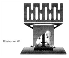
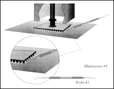
Removal Procedure: 1. Remove excess coating from the QFP leads prior to component removal. Use the pad prep cleaner included in the Motorola 81-30303-E45 SMD Tool Kit. Note: Replace the prep cleaner nib every 2-3 component removal prep cycles, or cut off contaminated tip end with razor blade. 2. Set the temperature control on the ChipmasterTM to 510°F for Bravo Express, or 450°F for Encore, and set the timer to zero. To set or change setpoint temperature, press the INDEX key on the controller TWICE; then press either the “UP” or “DOWN” arrow to reach the desired temperature (RED L.E.D. display). To do this, use the “UP” arrow to increase: hold the button in to increase rapidly. To increase temperature in one-degree increments, press the arrow button in individual steps. The same procedure works for the “DOWN” arrow button. Then press ENTER. Press the INDEX key one more time to return to the operational menu. To reset the timer to zero, press the ENTER key and the “DOWN” arrow key simultaneously. The display will flash once, indicating that the timer has been reset to zero. How the Timer Works: When a specific time has been set, i.e. 60 seconds, the Chipmaster’s timer counts down to zero once the foot pedal to start the heat cycle is depressed. The timer will stop at zero, even if the the heating continues (foot remains on the pedal). If the timer is reset to zero, it will begin counting UP once the heat cycle begins and will STOP counting once the cycle is stopped by the operator (foot pedal released). The timer will display the cycle time, i.e. 45 seconds. Each time the foot pedal is depressed to start the cycle thereafter, the timer will count DOWN to zero from whatever the cycle time (in this example, 45 seconds) was recorded. The procedure for changing cycle time is similar to setting temperature. 3. To Set Time: Press the INDEX key ONCE (from the operational menu) to reach the timer set menu. Use the “UP” arrow key to increase time in one-second increments; hold the button down to increase rapidly. Once the time is set, press ENTER; then press the INDEX key TWICE to return to the operational menu. 4. Install the appropriate nozzle in the Chipmaster; 1″ x 1″ for Bravo Express, 1/2″ square (vented) for Encore. 5. Center the chip under the Chipmaster heating nozzle as shown. 6. Depress the foot pedal to start the heating cycle. Note that the GREEN display will begin “counting” the seconds while heating. The RED display will indicate the heated air temperature as it ramps. 7. Turn on the vacuum pump, then depress the vacuum pickup assembly to capture the component. The component will not, however, lift off at this time. 8. After 45 seconds of heat application, use the probe #2 from the SMD Tool Kit to apply slight positive pressure under the component to gently break the bond of the coating as the chip ramps up in temperature. 9. As the coating continues to soften (approximately 50 seconds duration for Bravo Express, 30 seconds for Encore), it will be possible to slide the probe completely under the chip. Continue to loosen the chip gently, releasing it from the bond of the coating all around as shown. Be careful not to attempt to force the probe under the chip; as the coating softens, the probe will slide under the chip easily. Since the coating thickness may vary, the softening time may vary as well. 10. After approximately 1 to 1.15 minutes, the chip, loosened completely, can be lifted off the surface by the vacuum pickup and drawn up into the nozzle of the Chipmaster. Release the foot pedal to stop the heating cycle. The GREEN timer display will stop counting, and will indicate the length of time elapsed. 11. Remove the board holder arm assembly from under the nozzle. Position it so that when the vacuum is turned off, the chip will drop onto the arm assembly. 12. Turn off the vacuum pump, using the switch on the front of the Chipmaster. The component should release and drop onto the arm assembly. Use a vacuum pickup wand to remove the component from the arm. 13. Depress the board holder piston (cylindrical top of the board holder); remove the entire board and holder from beneath the nozzle assembly by sliding the whole assembly sideways and out from beneath the nozzle.
|

Like Us


