 Shop Online
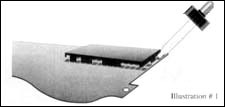
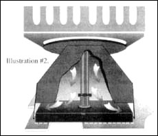
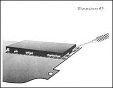
PA Module (LMPS) Removal and ReplacementRemoval Procedure 1. Flood area with wetting solution (66-80333E73) prior to component removal, using “eye dropper” found in Motorola 81-30303E45 SMD Tool Kit. 2. Set the temperature control on the Chipmaster to 430°F. Reset the timer to zero. To set or change setpoint temperature, press the INDEX key on the controller TWICE; then press either the “UP” or “DOWN” arrow to reach the desired temperature (RED L.E.D. display). To do this, use the “UP” arrow to increase: hold the button in to increase rapidly. To increase temperature in one-degree increments, press the arrow button in individual steps. The same procedures works for the “DOWN” arrow button. Then press ENTER. Press the INDEX key one more time to return to the operational menu. To reset the timer to zero, press the ENTER key and the “DOWN” arrow key simultaneously. The display will flash once, indicating that the timer has been reset to zero. How the Timer Works: When a specific time has been set, i.e. 60 seconds, the Chipmaster’s timer counts down to zero once the foot pedal to start the heat cycle is depressed. The timer will stop at zero, even if the heating continues (foot remains on the pedal). If the timer is reset to zero, it will begin counting UP once the heat cycle begins and will STOP counting once the cycle is stopped by the controller (foot pedal released). The timer will display the cycle time, i.e., 45 seconds, or whatever. Each time the foot pedal is depressed to start the cycle thereafter, the timer will count DOWN to zero from whatever that cycle time (in this example, 45 seconds) was recorded. The procedure for changing cycle time is similar to setting temperature. 3. To Set Time: Press the INDEX key ONCE (from the operational menu) to reach the timer set menu. Use the “UP” arrow key to increase time in one-second increments; hold the button down to increase rapidly. Once the time is set, press ENTER; then press the INDEX key TWICE to return to the operational menu. 4. Install the PA (Motorola #66-80333E28) nozzle in the Chipmaster. CAUTION! After removal, do not touch or move the module, as jarring or moving while hot could cause a P.A. failure. 5. Center the P.A. under the Chipmaster heating nozzle as shown in illustration 2/2A. Be sure to observe vent and height position in illustration l. 6. Depress the foot pedal to start the heating cycle. Note that the GREEN display “counting” the seconds while heating. The RED display will indicate the heated air temperature as it ramps. 7. Turn on the vacuum pump, then depress the vacuum pickup assembly to capture the component. The component will not, however, lift off at this time. 8. After 1:40 seconds of heat application, use the probe #2 from the SMD Tool Kit to apply slight positive pressure under the PA to gently break the as the PA ramps up in temperature. Illustration #3. 9. As the solder continues to heat (approximately 1:20 seconds duration), it will be possible to slide the probe completely under the PA. Continue to loosen the PA gently, releasing it from the bond. Be careful not to attempt to force the probe under the PA; as the solder becomes molten, the probe will slide under the PA easily Since the nozzle and PA position may vary, the softening time may vary as well. 10. After approximately 1:20 to 2.15 minutes, the PA, loosened completely, can be lifted off the surface by the vacuum pickup and drawn up into the nozzle of the Chipmaster. Release the foot pedal to stop the heating cycle. The GREEN timer display will stop counting, and will indicate the length of time elapsed. 11. Remove the board holder arm assembly from under the nozzle. CAUTION: Do not turn off the vacuum or move the PA. 12. Leave PA in position within the nozzle until temperature reaches 140°F. (red LED) 13. Grab cooled PA with tweezers from Motorola Tool Kit. Turn off the vacuum pump, using the switch on the front of the Chipmaster. Replacement Prep 1. While the board is still warm, use the Prep Pen (Motorola #66-80333E75) supplied with the SMD Tool Kit to clean pad area, as shown. 2. Using cleaning solution IPA (Motorola #01-80303E39) from the tool kit, continue to clean the area being careful not to damage the pads themselves. 3. After cleaning, place a small amount of “No Clean Flux” (Motorola #66-80333E71) on the cleaned pads. Reinstallation of PA 1. Hot air level the pads. In most instances, sufficient solder will remain on the pads to attach a new PA; but the surface may be rough, uneven, or have solder “icicles”, making accurate placement of a new PA impossible. To hot air level, depress the foot pedal to begin the heating cycle. The GREEN display will begin counting DOWN to zero. The solder will melt and become smooth; the solder should cover the pad(s) completely, with a slightly rounded “pillow” shape. 2. Remove the board and board holder assembly from beneath the Chipmaster nozzle (depress cylinder, slide holder and board out). Let the board cool to ambient temperature. Note: If there is insufficient solder to cover the pad(s), add solder to the pad(s) using wire solder and a soldering iron. Apply a drop of Pad Prep Solution to the pad(s) first, and clean afterwards with Pad Prep Cleaner. 3. Using the white “No-Clean” (Motorola #66-80333E71) flux and Amber needle supplied with the SMD Tool Kit, dispense a small amount of flux on the PA pad area as shown. 4. Pick up a replacement PA using a vacuum wand from the tool kit and place and center the PA on the solderable pad(s). Be sure external leads align with pads. 5. Place the board itself under the nozzle of the Chipmaster, being careful to center the component under the nozzle as accurately as possible. 6. Press the INDEX key on the Chipmaster controller ONCE, and verify or enter the appropriate cycle time. The appropriate cycle time for installation is the removal time, plus 30 seconds, to ensure good solder wetting.
7. Depress the foot pedal to begin the heating cycle, until the timer reaches zero. 8. Release the foot pedal to end the heating cycle, and, after red temperature LED indicates 140°F., remove the board from the Chipmaster work area.
|


Like Us


